What is the Purpose of Open-Drain Interrupts?
An interrupt can be thought of as a type electrical “flag” that can be raised in an electrical system. Often times, an interrupt is used to tell some other device in a system like the MCU that an action must take place. This could be a read of information from a downstream peripheral like a temperature sensor, or a key-press from a keypad scanner circuit.
The image below is a typical use-case for handling interrupts from 4 different temperature sensors with interrupts in a system.
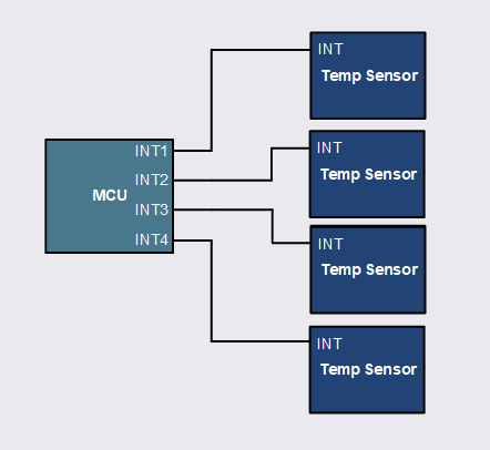
The MCU handles 4 different interrupt signals from 4 different temperature sensors
Interrupts are very useful in electrical systems. Either one of these temperature sensors can flag an interrupt back to the MCU. Maybe there is an over-temperature event from temperature sensor 2. This over-temp event can be signaled back to the MCU to alert of high temp in another area of the PCB, thus the MCU can shutdown electrical subblocks in that area to prevent any damage.
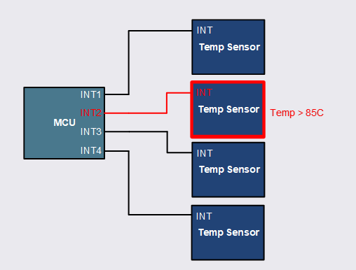
A temperature of 85C trips temp sensor 2, the MCU receives this interrupt. The MCU now knows that temp sensor 2 is over-heating
The down-side of the above implementation is that 4 GPIO pins from the MCU must be dedicated to each temperature sensor with an interrupt. In this case there are only 4 pins needed. You can imagine in larger systems where there are many temperature sensors on a board, the number of dedicated GPIO’s from an MCU can be limited.
Thus we introduce the open-drain interrupt.
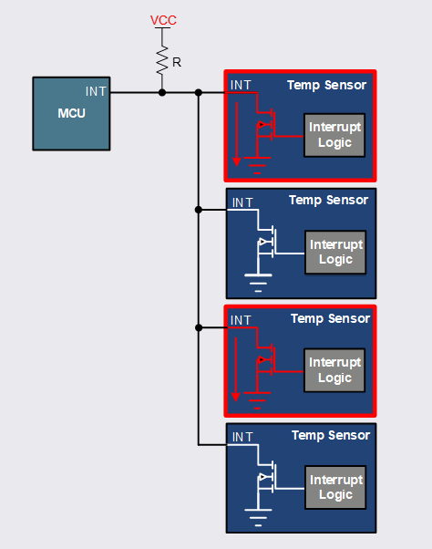
Open-drain interrupts
With open-drain interrupts, the number of inputs needed on the MCU reduces to a single pin.
No bus contention exists either. If temperature sensor 1 and 3 both pull LOW to GND at the same time, there is no over-current event because both pull LOW to the same ground potential.
The only down-side to this method of interrupt detection is the addition to software complexity. Instead of having 4 GPIO’s on the MCU, the microcontroller must check each temp sensor in a sequence in order to determine the source of the interrupt since any one of the temp sensors sharing the interrupt signal could be alerting the bus. The MCU will go down the line of temperature sensors and check each device for the interrupt flag only to find that temp sensors 1 and 3 are pulling the bus LOW. Thus, there is some time wasted checking temp sensors 2 and 4 since no interrupt has occurred.
This time wasted in most cases is negligible because the communication protocol used to communicate to devices like temperature sensors is fast enough. I2C or SPI can operate in 100’s of kHz of speed. By checking 4 temperature sensors in a row, it might only take 10’s of micro seconds in order to poll through each device which is fast enough for most temperature detection applications.