I2C Buffering - How to use TCA9517A
The I2C bus standard by NXP has specific rise-time and capacitive loading requirements for each mode of operation. The three most common modes of I2C operation are standard mode, fast mode, and fast mode+. See the table below for the system level requirements for each of the three modes:
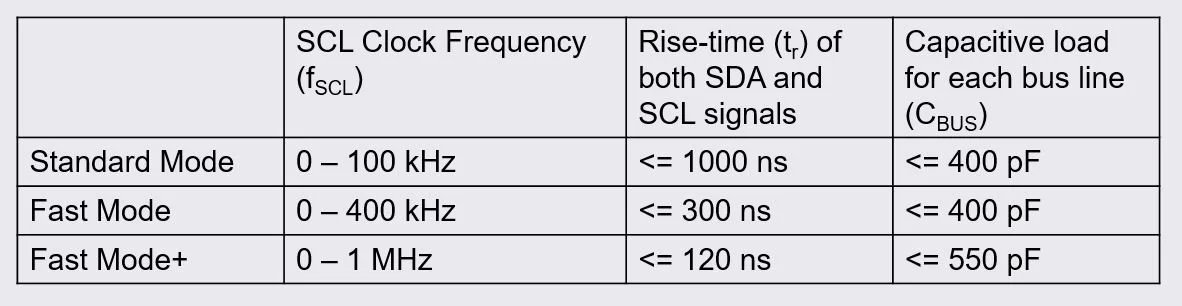
3 Most Common Modes of I2C Operation
Each mode is limited by a specific bus capacitance load. In most I2C cases, the load per bus line (SDA / SCL) must stay below 400 pF to be within I2C specifications. Bus loading is accrued most commonly by trace capacitance in a PCB plus any input capacitance from multiple controllers and targets in an I2C bus system.
The image below shows an I2C controller connected to 40 other targets in a single I2C bus system. If you estimate that each controller and target in the system has about 10 pF of input capacitance, you are already above the limit suggested by the I2C standard.
CBUS = C(controller) + 40 x C(target) + C(PCB_trace) > 400 pF
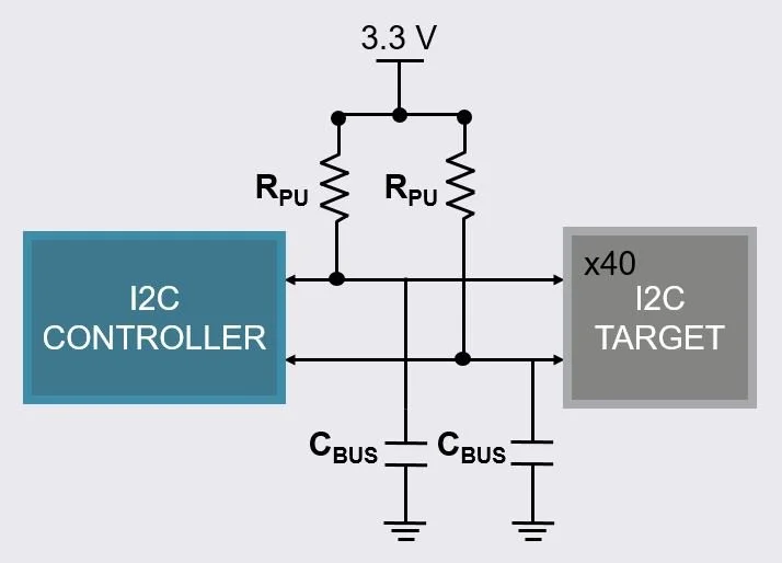
I2C Controller + 40 target devices can easily accrue bus capacitance > 400 pF
In the case an I2C system exceeds the bus capacitance limit, a buffer will be required.
Other common names for buffers in I2C are repeaters and re-drivers.
The image below is an example block diagram of using Texas Instruments TCA9517A I2C buffer.
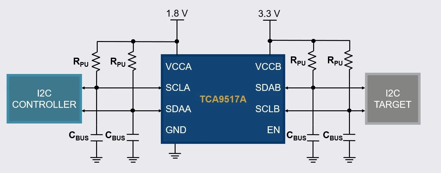
Example use case of TCA9517A - Level Shifting I2C Bus Repeater
TCA9517A is an 8-pin I2C buffer/repeater from Texas Instruments. This device can buffer I2C signals and level shift (aka voltage translate) from two different voltage levels (i.e. 1.8-V to 3.3-V) at the same time.
The device separates two I2C bus segments separating current and therefore separating capacitance i.e. buffering. This method of implementing an I2C buffer allows the user to expand their I2C bus by having 400 pF on each side of the buffer, totaling for 800 pF.
A FM+ buffer such as TCA9617B can have 550 pF of capacitance on each side of the buffer allowing a capacitance budget totaling 1100 pF all at 1 MHz clock speed (SCL).