What is an open-drain circuit?
Below is a simple open drain circuit with an open-drain driver connected to an RC load.

3.3 V is the supply voltage.
R = pull-up resistance
C = capacitance load
Vout = voltage output measured at the drain of the pull-down nFET
The open-drain driver acts like a switch to GND
When the switch (open-drain driver) is OFF, the capacitor is charged to a VCC = 3.3V through the pull-up resistor. If given a long enough time, Vout = 3.3V. The capacitor looks like an open-circuit. In this case, we assume no current leaks to GND through the nFET transistor.
When the switch is ON, the open-drain driver pulls strongly to GND, discharging the capacitor. The nFET sinks current through the pull-up resistor also. Vout will measure a voltage close to GND. Vout is “close” to GND because there is a small series resistance from the nFET (RDS_ON = resistance from drain to source). Therefore, Vout never equals 0 V.

Capacitor discharges through the low impedance path created by turning ON the pull-down FET
We can graph the voltage to get a better idea of what is happening.
In the first case, the capacitor is charged to 3.3V.
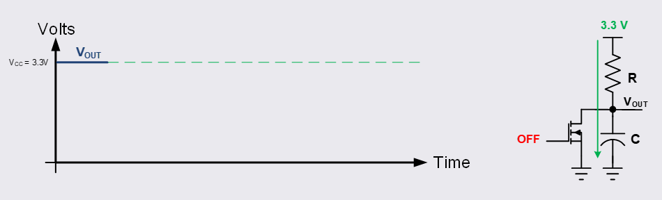
Vout measures 3.3V, since capacitor is charged fully and looks like an open-circuit.
From an idle state, the nFET turns ON and begins to discharge the capacitor rapidly.
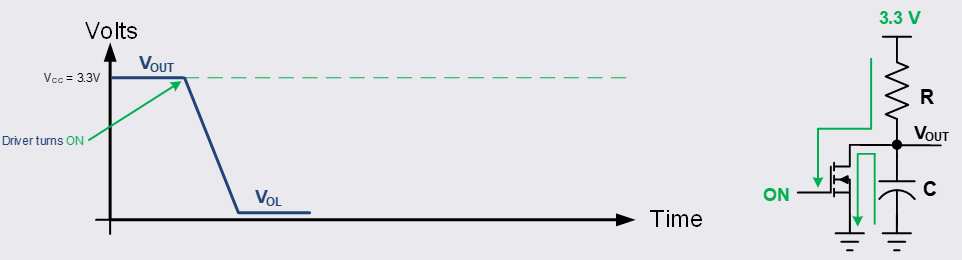
The open-drain driver discharges the capacitor to a VOUT = VOL.
VOL = voltage output LOW. Since there is a small ON resistance between the drain and source of the pull-down nFET (RDS_ON), there exists a small voltage drop. For this reason the output voltage Vout ≠ GND.
In the final state, the open-drain driver switches to the OFF position, turning off the nFET. This takes us back to the original case where the capacitor begins charging back up to VCC through the pull-up resistor.
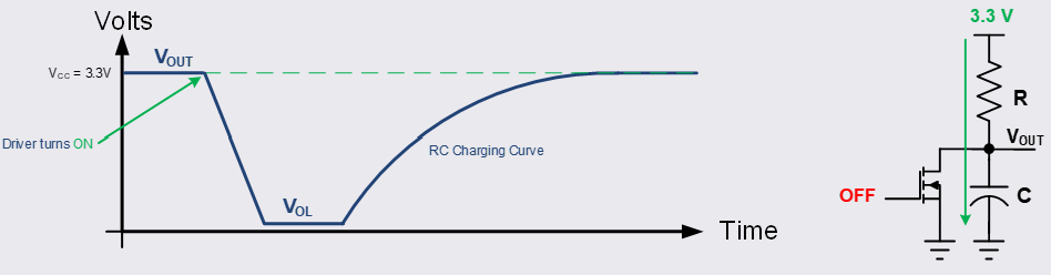
The open-drain driver turns OFF and becomes high impedance. The capacitor charges through the pull-up resistor with an RC charging curve.
***Note that the open-drain driver drives strongly towards GND. When the open-drain driver turns OFF, the capacitor charges slower towards VCC. This indicates that the resistance of the open-drain driver is much smaller than the resistance of the pull-up resistor. You can think of it this way, a pull-down FET of 100 ohms of strength drives towards GND much faster than a pull-up resistor of 10k ohms towards VCC. This is a common topology is protocols like I2C/I3C, and other open-drain outputs on various semiconductor devices.