Arduino - How to Use Photo Resistors
A photo resistor is a passive component that decreases in resistance when exposed to light. More lumens = less resistance.

The Photo Resistor!
We can use a photo resistor to detect “darkness” or a decrease in the amount of exposed light.
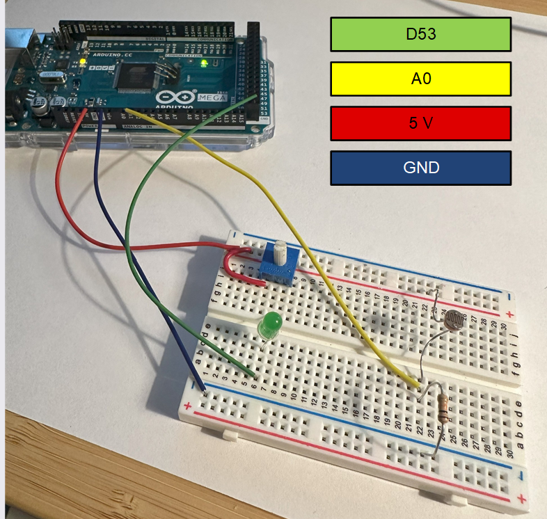
Arduino Setup
Digital pin 53 (green wire) is connected to the cathode of a green LED. The potentiometer is used to limit the current flow through this LED.
Analog input A0 (10-bit ADC) is connected in between the photo resistor and 10 kΩ resistive divider (yellow wire).
5 V power supply input (red) is connected to the positive rail on top of the breadboard.
GND (blue) is connected to the negative rail on the bottom of the breadboard.
Schematic:

Complete Schematic
Code:
The example code below sets up the 10-bit ADC on A0.
GPIO 53 is set to an “OUTPUT.”
The analog value of A0 (0 to 1024) is read and printed to the serial monitor. When light is present, the ADC reads ~750 in my setup.
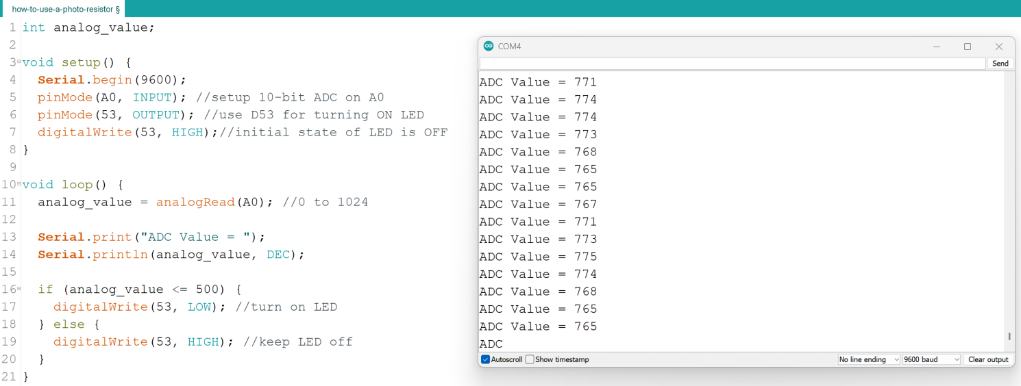
When light is present, ADC value reads ~750.
When I create a shadow with my hand over the photo resistor, the ADC value drops to ~460.
Therefore, I setup an “if statement” so that any ADC value of 500 or less will turn on the green LED, indicating the presence of less ambient light, i.e. my shadow.
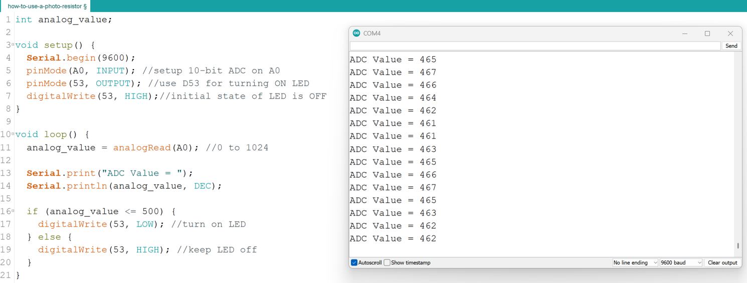
My shadow drops the ADC value <500. When the ADC value drops below 500, I turn on the LED via digital output pin 53.
Turning ON the LED with my shadow using a photo resistor
Example Code:
int analog_value;
void setup() {
Serial.begin(9600);
pinMode(A0, INPUT); //setup 10-bit ADC on A0
pinMode(53, OUTPUT); //use D53 for turning ON LED
digitalWrite(53, HIGH); //initial state of LED is OFF
}
void loop() {
analog_value = analogRead(A0); //0 to 1024
Serial.print("ADC Value = ");
Serial.println(analog_value, DEC);
if (analog_value <= 500) {
digitalWrite(53, LOW); //turn on LED
} else {
digitalWrite(53, HIGH); //keep LED off
}
}